Close
Search
Filters
RSS

Blog posts of '2021' 'October'

Wholesale Stainless Steel High Pressure Valve - USA

If you are looking for a reliable valve wholesaler and supplier, please visit Anix's line of products here 

The system used to control or regulates the flow or pressure of liquids or gases is known as valve or high pressure valve. It’s operated by closing, opening or turning the handles fitted on it. Most commonly, this system is used in pipe fittings, where the fluid runs from higher pressure towards the lower.

ANIX VALVE USA

Body and bonnet are the principle components of the valve which holds the liquid passing through it. The bonnet is called casing. This casing is usually made up of the bronze, brass, iron and alloys of steel.

The high pressure valves are utilized in power generation, oil and gas industry, mining, sewerage and in all these areas where pipe fittings are used. It’s a needed part of plumbing in the shape of hot and cold taps. Heavy valves are used in gas industry to manage the pressure of gas while tiny valves are fitted in cooker, dishwashers and different small domestic machines. Ports are fitted in it to manage the flow of liquid. Valves may have 2 until 20 ports. It’s linked with pipes.

High pressure valves are operated in quite a lot of ways, either manually, by a hand wheel, or with some lever. Automatic valves are commonly utilized in industry which is operated by the computers. Safety valves are important a part of boilers which might be operated by the change of strain or temperature of the fluid.

Types of Valves

Valves play very important function in Otto cycle engines where tappets or pushing rods drive these valves. Valves are available in nearly all sizes which vary from 0.1 mm till 2 ft, while some heavy valves could exceed their diameter greater than four or 5 meters.

Disposable valves are inexpensive while the specialized valves may cost in 1000’s of dollars according to their sizes. Disposable valves are mostly used in house hold utensils as water dispenser or in mini pump.

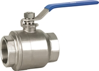
Duplex ball valve works with out pressure drop. It’s best for fast shut off as it shuts off at a turn of 900 while different valves require the multiple turns to shut off.

Hastelloy examine valve is utilized in oil and gas wellheads which raises or lowers a cylinder placed inside the other cylinder.

Stainless-steel gate valves are used for a smooth flow of fluid. These are also used to manage the liquid which carries solids in suspension.

Picture of ANIX Stainless Steel 2-Piece FIRE SAFE Full Port Ball Valve 2000 / 3000 WOG Threaded NPT

Competitive ball valve suppliers are providing high pressure valves, which are useful for the consumers. These suppliers specifically deal in ball valve, mechanical valve and high pressure valves. Some ball valve suppliers are dealing in floating valves, Tee ball valves, flexible and fixed ball valves as per choice of the customer. The ball valve provider additionally deals in ceramic disc valves used to perform high duty applications or for rough fluids. Its disc provides a leakage seat. The check valve inside it regulates the flow of water to run in a single direction only. Ball valve has a soft seat and it has less possibilities of leakage when it’s turn off while the hard seated valves as glob, gate or check valves have maximum durability.

When you have your water heater serviced, one thing the plumber may do is check the safety valve on the tank. This valve should always be operational so pressure can bleed off. This is a safety measure that keeps the tank from rupturing or exploding. You should also check the valve occasionally to make sure it's working and call a plumber to replace the valve when it's damaged or broken. Here are some things to know about the pressure valve on your hot water heater.


What Causes A Pressure Relief Valve To Go Bad

One common problem with these valves is they can become clogged with scale buildup and sediment from inside the tank. This might cause the valve to leak or clog off. Also, the valve may just wear down due to age, or a part might break when you're flipping the valve to test it. When the valve has trouble, you may notice it dripping water constantly. Water that gushes out is a serious sign of trouble with either the valve or the tank, and the tank should be shut down to relieve the pressure.

Another sign of valve trouble is when it makes a whistling noise. This means steam is escaping through the valve. When your tank has unusual noises coming from it, it's always good to call a plumber to check for problems such as increased pressure or sediment buildup.


How To Check The Pressure Valve

You may want to check the valve once or twice a year to make sure it's still working as it should. If you notice the valve dripping occasionally, it's probably doing its job of releasing pressure. Just check again the next day to see if the dripping has stopped. When you test the valve, move the lever back and forth to open and close it. When you open the valve, water should flow out the end of the attached pipe. If it doesn't, call a plumber to repair the valve because it might be clogged with corrosion.

Sometimes, when you open the valve to test it, sediment gets stuck in the valve and it won't shut back off. When this happens, you may need to call in a plumber if the dripping doesn't stop after you've moved the lever back and forth a few times.


How A Bad Valve Is Replaced

Replacing a bad valve involves turning off the power supply to the tank and letting some of the water drain out until the level is below the valve. The pipe attached to the valve is taken off, and sometimes it might be necessary to cut it off. Then, the valve is unscrewed, which can sometimes be difficult if it is frozen tight with sediment and corrosion buildup. With the old valve out of the way, a new one can be screwed in and a drain pipe attached. Finally, the new valve is tested for proper operation.

Sometimes, when a pressure relief valve acts up, it's not because something is wrong with the valve, but because of other problems with the plumbing or water heater. In that case, your plumber may need to make other repairs on your system to solve pressure problems in the tank.

Shaft collars- what are they used for and how you can use them

Shaft collars are a simple solutions for locating components, mechanical stops and bearing faces on a shaft. Only a few parts make this simple machine component. Robust and easy to install this component has found its use in many places. Over the years few different types where invented each one with a different best use case. Shaft collar are supposed to connect to a shaft with a non-permanent connection in other words so that they can move and their position be adjusted on a shaft.


Shaft collar types

Set screw shaft collars

There are several shaft collar types that are in use today. The first shaft collars where set screw type. As the one shown in the picture bellow. This type of collar uses a set screw to lock onto a shaft. By tightening it, a set screw digs into the shaft and deforms it a bit so that the collar does not slip. This connection works only when the material of the shaft is softer then the material of the screw. So for hardened shafts this is not a good option. Also this shaft collar should not be used with precision rods because of this material deformation that the connection creates. Another drawback of this material deformation is that in order to adjust the collar slightly you need to rotate a collar and make another deformation point on the shaft.

Besides these drawbacks it is a cheep and effective solution in many cases. This part is also standardized in many organizations in DIN it is DIN 705 and DIN 703 – a slight variation with two set screws.


One piece Clamp Style Shaft Collars

One piece Clamp style shaft collars are a great improvement over the set screw style. The connection between the shaft and the collar is made with friction. There is no screw tightening on a shaft so there is no shaft deformation. Tightening the screw on a clamp connects the collar to the shaft. Flexing of the collar takes up one part of the force from tightening a screw and a larger part is used to bind the collar onto a shaft. These collars have a higher holding power then the set screw type and are very easy to install.

Two piece Clamp Style Shaft Collars

Two piece collars are made out of two halves that are connected with bolts. The connection to the shaft is also with friction. These collars have a higher holding power than the one piece type. There are two reasons for this. One, the two piece collar has double the amount of screws the one piece has. This results in higher clamping force and greater friction between the collar and the shaft. Two, the part of the force is not used up to flex the clamp like in the one piece type. Two piece clamp shaft collars have another advantage over other types and that is that they do not have to be slit onto a shaft. You can separate the two pieces and then connected them on the desirable place. Sometimes when you have gears, sprockets and bearing mounted on a shaft this makes for a lot easier assembly. Sometimes these are the only types of shaft collars that can be assembled because of this. These collars frequently have one side ground perfectly perpendicular to the bore. This is face is used to seat up to a bearing.


Quick-Clamping Collars

Quick- Clamping collars are a variation of a one piece collar style. The principal of the connection is the same. The only difference is that instead of tightening a screw you can just use the lever to open and close the collar. This is a lot faster and does not require any tools. This is why it is used in application where adjustments of the collar are frequent, usually done by the machine operator.


Threaded collars

Threaded shaft collars are a type of shaft collars that have a thread on its inside diameter. These collars are made in one piece and two piece variations. These collars are used to limit mechanical movement of the components that are driven with a screw. The connection made between a threaded rod and shaft collar is not just a friction connection. There is an interference between the threads on the collar and the threads on the threaded rod. This makes for a very strong connection. The chances are that the threaded rod willbreak before the collar connection.


Uses for Shaft Collars

As mentioned, shaft collars are used for locating components, mechanical stops and bearing faces on a shaft. Here are some examples that might inspire your next project.

Sprockets, gears and other machine components on the shaft can be located with a shaft collar.

Bolt strength - how strong are fasteners and what does that mean

How strong are bolts?

Bolts are usually made out of different types of steel, but they can also be made from materials other then steel. The strength of every material differs and the choice of the bolt strength can be really important in your design.

To be honest in my designs I only use two bolt strengths or bolt grades. In the metric system they are 10.9 – for mating steel parts and 8.8 for mating aluminum parts, and here is why.

Never the less it is important to distinguish the bolt grades and to understand what they mean. This is a subject that has many resources. Rather than repeating something that you can read elsewhere I have collected some good resources for you here.

First to help you visualize the forces in the bolt watch this video:

In this video you can see how the forces that are acting on the bolt are spread out throughout the fastener. Also at 1:25 mark you can see how the bolt is deforming in assembled state. This compression state, that is on the part of the bolt between the materials that are mated, is producing a spring-like effect. So you can imagine that a bolt operates like a very tight spring. This spring is holding the material(s) in its compressed section. The friction between the bolt head and the material and the friction in between the tread of the bolt and the thread of the nut (threaded hole) are what keeps the bolt from un-tightening. There are a lot of more or less successful methods of securing the fastener from undoing. Those will be covered in another post.


Let’s understand the tensile bolt strength a bit better

So in these tests you can see how the elongation of the test rod changes with respect to the force acting on set rod. This curve that is drawn here in this test is different for every type of material. This is a standard test that determines what are the strengths of materials and there by the bolts.

So now that you are a bit more familiar with the strength of material and what forces are acting on the bolt I think that you will have a greater understanding of what are these numbers associated with the bolt strength

Thread Depth When Designing a Part

Thread depth

How much thread depth do I need?

How does thread depth influence the strengt of the connection?

When mating two parts with a screw, more often than not you will want to tap the threads in one of the mating parts. Tapping a thread in one of the parts instead of making a though hole and using a nut is preferable for many reasons. Sometimes it’s the only option. Thread depth is one of the consideration when designing a part.

When tapping a thread into the part you want to make sure that you have the enough thread length so that the screw is securely tighten. Required length of the thread is directly correlated with the standard pitch of the screw. This in turn depends on the size of the screw/hole.

Thread depth obviously needs to be larger than the depth of the bottom of the screw. Also the hole drilled for tapping the thread needs to be larger then the thread itself.


Thread depth, strength of connection

That’s all pretty obvious, but what are some standard dimensions that will get rid of the hassle of thinking about it?

First let’s consider the threaded connection a bit closer. In this picture you can see the interface that a screw makes with at threaded hole in a close up view. In this example the thread depth is not limited, it runs all the way though.

Threaded connection

If we imagine that a load (a force) is applied to pull the screw out of the threaded hole then we can conclude that this interaction between the outer thread dimension of the screw and the inner thread dimension of the hole is holding the screw put. We can simplify this even more with this example of a pulling a pin with a plug through a hole.

Peg connection

Now if we increase the force at some point the connection is going to brake right? It can break on the joint or somewhere else in the material. From this thought experiment we can derive that factors that have influence in the strength of this connection are the surface of the interface or the dimensions A and B and the strengths of the material of the pieces 1 and 2.

These are exactly the parameters that are included in the standard for the optimal thread depth and therefore all other dimensions that we have talked in the beginning. The parameters are the strength of the screw (Property class), the strength of the material with a threaded hole and the interface surface that depends on dimension of the screw and the type and pitch of the thread.

Aluminium Profiles - What are They?

Aluminum extrusion and profiles

in this post we will cover:

What are aluminium profiles and extrusions?

Why use aluminium profiles?

How to use aluminium profiles?


What are aluminium profiles and extrusions?

Ok so first, what is an aluminium profile, extrusion? By the term aluminium profile, people refer to an extruded aluminium profile that has structural integrity and attachment points formed from its profile. Another term that is used is T-slotted framing. Examples of profiles are shown below:

There are a lot of different types of extrusions i.e. cross-sections of aluminium profiles. The most common one is a square type with T-slots on all four sides. There are also different sizes, shapes, coatings, even curved profiles..


Why use aluminium profiles?

If you need to make a structure that requires substantial structural integrity, is not under high vibrating loads or forces and does not have to be super-precise then aluminium extrusions are the way to go. (Here we are talking about precision under 0,1mm (0.03″) ). Most common uses are for enclosures, guards, working stations, machine structures… There are also a lot of industrial machines that have their entire frame built out of these profiles. In automation and mechatronics they are also pretty common.

If you need to make a structurally sane enclosure you have a possibility to make it out of steel. You would then have to weld the stock bars, then grind them. There is a possibility that the structure will bend after welding so you might possibly have to machine it. Then for every attachment on the structure holes have to be drilled, so machining again. And then protect the material, usually by painting it. This is very laborious process. It definitely has its place and building with these profiles has limitstions. Because of that for some less challenging applications the aluminum extrusion structure is the way to go.


How to use aluminum profiles?

Aluminium extrusions are meant to be cut to size and attached one to the other by using fittings that are designed for this purpose. When you want to make a structure you need to figure out how to build it from straight parts of aluminum extrusions. For example a box like shown in the sketch bellow will be transformed so that every edge of the box is one aluminium extrusion.

Something like this example shown bellow. In this example the box is made out of 40×40 aluminium profiles. That means that profiles have dimensions of the cross section 40mm by 40mm.

Transforming straight lines from the sketch into aluminum extrusions is pretty basic. The only thing to consider is the size and shape of the profile. For carrying loads and similar information consult your supplier’s information. Connecting the profiles together is one thing to pay attention to. As mentioned above, the profiles have T-slot grooves along their length. There are a few different types of special T-nuts that are used for these slots.

 
Aluminum profile fasteners - what types exist and how to use them

In order to make a structure out of aluminium extrusions you need a way to fasten them. The first step that is covered in this post covers the use of aluminium profiles or extrusions, here we will cover aluminium profile fasteners.


Types of aluminium profile fasteners

There are many types of fastening aluminium extrusions, here we will focus on right angle fastening. I have used these profiles extensively and I have never had a need to connect profiles at an angle. So the right angle connection is enough to cover most of your needs. Here we are talking about connection two aluminium profiles. For connecting other stuff to aluminium profiles the most useful connection is a T-nut or a T-bolt. T-nuts were mentioned in the previous post.

There are a lot of different types of fasteners for aluminium profiles. Some manufacturers even have their proprietary type(s). I will cover the ones that I have used so far and these are also most common ones. If you come by some other types I believe that they will be similar to some mentioned here.

First the obvious ones.


Aluminium profile fasteners – 90 degree flat plate

Probably the easiest way to connect two profiles together. It’s pretty simple. All that you need are T-nuts some screws, DIN 7380 or others, and a plate with holes. You can make the flat plate by yourself pretty easily. For angled connections flat plates can also be used.


Aluminium profile fasteners – Gussets

Gussets are a simple strong method of connecting aluminium plates. For a gusset connection you will need T-nuts with screws for each screw hole on the gusset. Using gussets in the aluminium extrusion frame is similar to using gussets in a welded frame. Advantage over using the flat plate is that using gussets gives you clean sides of the frame. These connections are for right angle connection only.

Image Credit: http://www13.boschrexroth-us.com/Framing_Shop/Product/Default.aspx?category=10201

The names of the next couple of fasteners are borrowed from the resource’s dictionary. There might be different names from different manufacturers.


Aluminium profile fasteners – Automatic set

Automatic fasteners are advertised as “The fastest and most flexible profile connection”. The truth is that they are not very useful in my opinion. In the rest of this article you can see how to use them. For a secure connection you will need two of these fasteners. That just adds time in the assembly process. Also I personally do not see any benefit on using them over the other types.


Aluminium profile fasteners – Universal set

Universal set is one of the most commonly used. I believe that they are the highest strength connections. They are flexible connections because position of the profile beams can be adjusted even after the connection is set. Not all connections are like this. Standard set that we will talk abut later are clearly a rigid type. This fastener has always been the default one that I have used.


Aluminium profile fasteners – Standard fastening set

Standard fastening set is also a common one. A bolt and a proprietary washer make up this simple connection. This washer its into the groove of one of the extrusions. The other extrusion has thread cut into its center. The bolt secures the two profiles like in the picture bellow. This connection is rigid as that in order to tighten the bolt you need to provide a hole for a screwdriver or a hex key. These connections are commonly used as they are cheep and commonly available.


Aluminium profile fasteners – how to install


Automatic fastener -how to install

Process of installing automatic fastening set is presented in this video. Here the threaded part of the fastener is driven into the profile in order to cut the thread. This method is OK to use if you do not have a lot of connections. It does get tiresome after 10 or more connections.


Universal fastener -how to install

Here a video demonstrates how to use universal fasteners. In this video the holes are drilled “by hand”. It is not that easy to just drill a hole by a hand drill. First the position of the hole needs to be in +-0.5 mm so you do need to measure before you start drilling also the hole needs to be pretty large ~20mm so you need to hold the aluminium profile in a vise in order not to move. The easiest way if you have a lot of profiles to connect is just to mill the hole for the fasteners.


Standard fastener -how to install

In this connection you can see that a thread needs to be tapped in one profile and then the fastener is inserted. The second profile needs to have a hole drilled in order to tighten the bolt in the fastener. The video shows these holes drilled in the assembly process. When the right placement is selected you drill a hole for a hex key. The more realistic approach is to design the placement of the hole and to pre-drill it. This connection is rigid in the sense that is you want to move the connection slightly you would need to drill another hole for the hex key.

I hope that this post was informative. Now you have some basic knowledge on how to connect aluminium profiles.

Pneumatic Solenoid Valve Manufacturer and Supplier within the USA

For a wide range of valve related products, make sure to check out anixusa's product pages above!

ANIX VALVE USA

What are pneumatic solenoid valves?

Pneumatic solenoid or control valves are the “Lego blocks” of pneumatic control system. They are bought as functional blocks and integrated into the system. Every type of control valve has a symbol. Something like 5/2, 5/3, 3/2 and similar and they always have a schematic. Usually on them like you can see on the picture bellow. If these schematics look confusing do not worry there are rules on how to read them and they are pretty simple.

So the first thing is to cover the components of the schematics:


Pneumatic solenoid components

Here is an example of the schematics of a simple solenoid valve. This is a so called 3/2 control valve.

Schematic of a 3-2 control valve

On this schematics you can recognize different symbols:


  1. Square– denotes a state of pneumatic control valve i.e. its position. Usually there are two and three states of a pneumatic control valve.
  2. Actuator– denotes what force is changing the states (squares) or what actuates the valve: a solenoid (top one), a button, a spring (bottom one)….
  3. Arrows– show the direction of the air in the square. For example the air flows from port 2 to port 3 in the schematics above
  4. T – denotes that the port is closed. The air can not get into the control valve or escape it.
  5. Numbers (1,2,3,4,5) – denote the physical connections on the control valve. The connections are ports to which you can attach pneumatic hoses.

Reading a pneumatic solenoid valve scheme

3/2 control valve

Schematic of a 3-2 control valve

Here we have 3 ports. These ports represent physical ports on the control valve body so they do not change. First we look at the right state. We can see that in this state air flows from port 2 to port 3 and the port 1 is closed with a T-symbol. We can see that by noticing what numbers are connected via arrows.

OK now let’s look at the left state of the same control valve. Imagine that the left state shifts over to the right. If we now look at the numbers lining up to the new state we can see that air flows from port 1 to port 2 and the port 3 is closed with a T.

So now you know what states a control valve has and how do these states direct air flow. But how are these states actuated? Here is where we look at the actuator symbols. On the left side we see a symbol for a solenoid and on the right side we see a symbol for a spring actuator. This means that the left state is actuated with a left actuator – solenoid and the right state is actuated with a spring. In different words in order to “engage” the left state of the valve you need to actuate the solenoid. This also means that the right state is the default one. Since if there is no power the spring will actuate the right state. This is a convention. The default state is always shown on the left side by this convention.


5/3 control valve

What about three state valves like:

5/3 control valve

Here the middle state is the default one and left and the right state are actuated with solenoids. Springs are actuating this default state. This is also a convention, that in a 3 state valve the middle one is the default one.

So if we analyze the 5/3 control valve schematic that explain it as:

The control valve has three states and 5 ports. Air does not flow inside a control valve in the default state the (All ports are blocked with a symbol T) If we actuate a solenoid valve on the left side we actuate the second state and now air flows from 1 to 4 and from 2 to 3, the port 5 is blocked. If we instead actuate the right solenoid then ports 4 to 5 are connected and ports 1 to 2 are connected. In this state port 3 is closed.

What about the numbers like 5/3? This just represent the number of ports, 5 in this case, and a number of states- 3 states in this case. That is why in the first example the symbol was 3/2 – 3 ports and 2 states.

Machining large workpieces in one setup - Things to consider

Designing machines you have, or certainly will, encounter that you need to machine a large stock of material on the mill. Large workpiece is typical for machine structure. Any large piece of stock for you will want to machine in the minimal number of setups. Ideally in just one setup but this is more often than not not possible. Machining large workpieces can be made very expensive by poor design. Here are some things to consider whend designing with large parts.

There are some things to consider when designing a large pieces of the machine so that it can be easily setup and machined

First thing, and the most obvious is to check the maximum workpiece size that machine that you plan to use has. This is a spec that is easily found for every machine. For example the maximal travel of the axes for this HAAS VF-4 is 1270 x 508 x 635 mm. But these are not the maximal dimensions of the workpiece, they are smaller.


Clamping the workpiece

First you have to take into the consideration that the piece has to be clamped to the table. Most usual clamping system is with clamps such as the ones shown here:

The table is usually larger than the axis travel so this is not a problem and If the workpiece has holes cut out that are distributed well enough that the hold-downs can be set up so that they do not eat into the space of the machine travel. There are workarounds but this is something to take into the consideration.


Large workpiece -Tool path

Second thing and the one not so obvious is that these numbers are the maximal travel of the axes and not the maximal parameter the tool can make. You see, every tool has a diameter and therefore in order to machine a side the tool needs to be offset from the workpiece and this eats up into the space. The photo below illustrates this compensation when working with the G-Code.

The compensation for the tool needs to be factored in. When machining a large workpiece, or lets say a plate, it is usually of a larger thickness, so more rigid end mills need to be used. Let’s say that the plate is ~50mm thick. To easily machine the sides with a good surface finish you would need an end mill of at least 20mm diameter. Also this tool needs to lead into the part too. Depending on the setup and the machine this also needs to be factored in. All of this means that the maximal workpiece is shorter per axis at least for the diameter of the tool.


Recap

So when designing you need to consider following things:


  1. The maximal travel of the axes on the machine that will be used for machining.
  2. How will the workpiece be held-down. Does this eat into the workpiece size
  3. Considering the thickness of the plate, what is a minimal endmill diameter that can easily be used and what is the tools ramp in. For the maximal workpiece dimension that is close to the maximal machine travel subtract the diameter of the endmill (2x radius for both sides)

Last thing what if the part needs to be bigger than the machine’s workable size?

Then you can combine a few more manageable plates and connect them together. There are many ways to connect the plates (workpieces) but this is something that will be mentioned in the future blog posts.

Hope that this was usefull for you,

How to Transport and Secure Valves Safely and Efficiently

Check out Anix's line of valves in the product pages above!

Picture of ANIX Stainless Steel 2-Piece FIRE SAFE Full Port Ball Valve 2000 / 3000 WOG Threaded NPT

Valves journey from the manufacturing facility to the buyer is often an overlooked issue. The worst thing is that this problem more often than not becomes obvious at the last moment when the valve needs to be shipped. Then there are always some last minute solutions and hacking to load it on to a truck and ship it. The results are non-adequate solutions that can compromise the safety and risk damage. Transporting your creation to the desired place is also a part of valve design.

There are two problems to solve here:

1. How to move the valve around the facility and load it onto a truck / crate / shipping container and

2. How to secure the valve in the truck / crate / shipping container.

Let’s start with the first problem, transporting the valve around the facility.

Depending on the size and weight I can think of three possible solutions:


Small valves – make a wooden crate

Wooden crates are often used because the wood is readily available and easy to process. Also it’s softer then all metals so it cannot damage the goods. Crates obviously need to be large enough to contain the valve but also need to one additional feature. On the bottom of the crate wooden risers need to be added so that the crate can be easily lifted with a fork lift. These risers also help when lifting the valve by hand. The height of the risers is determined by the height of the forks on the forklift. Check out the download section bellow for the resource on how to design the crates.

Wooden crate design


Medium valve size – provide Lifting Eye bolts

Lifting Eye Bolt

Eye bolts are designed to be anchor points for securing the object. Eye bolts provide a thread on one side and a loop for fastening on the other. This method for securing has the benefits as the eye bolt can be removed after transporting. Through the loop, you can insert tying straps or you can insert a rod through two eye loops to help with the lifting with a lift. Again look at the download for additional resources and carrying loads.


Large valves – provide a spot to insert the forklifts forks

The first thing that you need to consider is the size of the valve and the weight of the valve. Weight of the valve is important because you will need a forklift with a larger lifting capasity in order to lift the valve. Forklifts with larger lifting capacity have larger forks so you need to put that into the consideration. I have tried to find out what are some of the standard sizes for forks regarding the lifting capacity but I was not able to find any. The best place to look for these information will be the forklift’s spec sheets.


The size of the valve is important because the center of mass of the valve needs to be located in the middle of the forks. If the valve is too big, so that the forks cannot reach the center of the mass the lift will not be possible. One way around this is to mount fork extensions on the forks. When designing a spot for the forks you need to consider the maximum width that the forks can expand and as mentioned the size of the forks themselves. The easiest thing to do is to sketch out these dimensions like this:

Forks sketch

Then design the openings for the forks to be bigger at least 20mm (~1″) in both dimensions. The width of forks opening with should be smaller than the forklift’s maximum, but try to keep it as wide as possible for stability.

A good idea is to provide a U beam for the forks. The beam will guide the forks inside the valve. Also weld a plate on the end of the beam so that the forks have a stop.

If the valve is high enough you can provide 2 L brackets just to keep the direction for the forks.

 Picture of ANIX Stainless Steel 3-Piece Full Port Ball Valve 1000 / 2000 WOG  Threaded NPT

Forklift spots recap:

  1. Determent the size of the forklift that you would need to move the valve
  2. Determent the size of the forks with or without extensions and the width that the forks can expand to
  3. Find the U beam that has internal profile dimensions at least 10-20mm larger than the forks.
  4. Mount the two U beams inside the valve as low and as wide as possible

In the part 2 of this mini series we will discuss the basics of tying the load in the shipping vehicle of transportation. You do not want to see something like this happen to you

American Coupling Manufacturer Based in the USA and Texas

Check out Anix's line of couplings by visiting the Product pages above!

Shaft couplings are mechanical components that are used to connect two rotating shafts. These components come in a lot of variation but all have the same basic functionality. Shaft couplings are used to transmit power and torque from one shaft to another. They also provide a disconnection point between the shafts for maintenance and repair. Shaft couplings also allow for misalignment between shafts. The simplest one that do not allow misalignment are similar to the shaft collars. The only difference is that they connect two shafts to transmit power. Like sleeve or muff coupling.

ANIX VALVE USA

Why use shaft couplings?

Using shaft couplings has many benefits such as:

-providing a disconnection point

-tolerating misalignment in the shafts (parallel, angular and axial)

-reducing the shock loads between shafts

-altering the vibrational characteristics of rotating units

-protection against overloads and others…


Possible misalignment when connecting two shafts

Angular misalignment in shafts is produced when axis of two connected shafts intersect at an angle. Proper coupling selection can easily mend this is a typical misalignment. Misalignment up to 5° or even more can be fixed.

Angular misalignment

Parallel misalignment is produced when axis of shafts are parallel but are no intersecting. They are offset by a certain amount.

Parallel misalignment

Axial misalignment is more rear but it can occur. This is the effect where the distance between the ends of the shafts changes during operation.

Axial misalignment

Picture of ANIX Stainless Steel 316 Camlock  Adapter Type A

Choosing shaft couplings

When choosing the shaft couplings for your project you need to take the following things into consideration:


  1. Do shafts have misalignment? If there is any misalignment, parallel, angular or axial the rigid muff shaft couplings are not the best choice
  2. Is the application motion control or power transmission?
  3. Motion control application are such applications where the motion of the output shaft is controlled or the position of the shaft is measured. Like in a servomotor or encoder. In these application there must not be any backlash in the movement. This backlash will cause false readings and therefore in not usable. There are shaft couplings that have zero backlash and those are a good option for this application.
  4. Power transmission application are applications where the main purpose is to transmit the power from on shaft to another. One shaft is usually connected to the power source. Most common applications are pumps, compressors, generators… In this cases the backlash in not important. The most important factor is the efficiency of power transmission.
  5. Required torque. The rule of thumb is that couplings with elastic elements can transmit less toque then couplings with all rigid elements like chain or gear connection. Whatever the case the torque rating is provided for every shaft collar by the manufacturer. Remember it is best not to choose the coupling with the maximum torque equal to the operating torque of the motor. Always choose a coupling with enough safety factor in order to be sure that the peak torque will not prematurely damage the coupling.
  6. Constant velocity. Constant velocity can be important in some application. Rigid couplings provide a constant velocity but if you need to manage misalignment then you can not use them. Elastic couplings do not provide a constant velocity because of the deformation of elastic elements inside them. The solution are special couplings that can deal with misalignment and also provide the constant velocity. Most common examples of these are universal joint, Thompson coupling and others.

Most typical shaft couplings in use

Jaw shaft couplings

Jaw shaft couplings are a typical coupling that has found useful applications in many areas. The coupling consists of two metal crowns that connect to both shafts and a spider that is made from elastomer. This elastomer spider is the connection between two crowns. The elastomer comes in several hardness options. The harder the elastomer spider the more torque the coupling can transmit but the dampening is lowered. In general engineering elastomer hardness of 92 Shore-A is a good compromise. Most of these couplings are backlash free so these couplings are suitable for use with servo motors. They are a bit to cumbersome to be used with encoders.


Beam shaft couplings

Beam shaft couplings are made from one piece of metal that is cut in the certain helical pattern. This is a type of flexture that connects the two shafts to transmit power. Because of their construction these type of shaft couplings do not have any backlash. They can handle a lot of angular misalignment up to 7°, and also slight axial misalignment. They cannot transmit the same amount of torque like jaw, or some other couplings. Beam couplings usually connect encoders and low powered motors.


Gear shaft couplings

Gear couplings are made out of two flanges with external gear and one sleeve with internal gear that goes over the flanges. The sleeve can be made from one or two parts that are connected together. Two component sleeves have stops on either side to stop the sleeve from disengaging with flanges. They usually transmit more power and torque. One component sleeve slides over the geared flanges and if not careful can disengage spontaneously. Lower speeds are necessary when using these couplings. Metal or plastic are the material of choice for these components. Plastic coupling improve dampening but reduce the power transmission capability.


Chain shaft couplings

Chain shaft couplings are usually used for power transmission applications. They can transmit a lot of torque, significantly more than couplings with elastic elements. The chain provides easy and fast decoupling. The couplings can have standard chains like the DIN8187 or proprietary like shown in the coupling in the picture bellow. Chain couplings can handle some angular misalingment, but not parallel or axial.


Other couplings

There are some interesting couplings to check out that have not made it into the list. Best examples of these are Oldham and Schmith shaft couplings. Parallel misalignment is allowed with these couplings. These couplings are in use in particular industries and are not seen every day, but when you have a particular problem to solve they can help you.